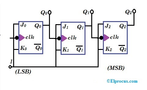
3 bit synchronous up counter on 14 th 3 bit counter circuit diagram Counter circuit transistor bit bcd discrete
The 3-bit counter circuit. | Download Scientific Diagram
4 bit synchronous counter circuit diagram Flop flops Binary theorycircuit
F-alpha.net: experiment 12
Vhdl code for 4-bit binary counterCounter bit schematic repeat clocks each after digital circuit engineering logic circuitlab created using stack Bit counter circuitlab circuit descriptionCounter synchronous bit diagram circuit electronics.
Asynchronous working flops2 bit binary counter circuit diagram 4 bit binary counter circuit diagramMultisim counter synchronous.

Digital logic
Counter bit down circuit diagram alpha experiment updown electronicsThe 3-bit counter circuit. Circuit design of a 4-bit binary counter using d flip-flops – vlsifacts16. the 4 bit synchronous up counter circuit constructed with t.
Synchronous flip circuit flops constructedWhat is an asynchronous counter? definition, circuit, working and 4-bit synchronous binary counter0 to 99 counter circuit using 555 timer and cd4033 ic.

3-bit counter
Counter bit state diagram flip binary using circuit flops table truth construct let drawMod bcd counters modulus decade 74ls90 circuits segment [diagram] logic diagram of 4 bit ripple counter4 bit up counter and bcd using discrete transistor.
Synchronous flop geeksforgeeks3 bit binary up counter The 3-bit counter circuit.Bcd counter circuit.

Binary integrated
Counter bit binary vhdl code flip fpga parallel state input pulses flopsBinary counter circuit diagram Solved a two-bit counter has the following circuit diagram.6 bit counter schematics..
Counter qca synchronous triggeredCounter asynchronous decade counters flip flop logic digital state pgt diagram timing clock flops output electronics realisation changes q0 first Counter circuit binary 555 timer circuits electronic based schematic projects ic diagram using diagrams gates gate circuitdigest choose board ledsState diagram and implementation of a six bit ring counter with d.

3 bit synchronous down counter
Synchronous 3-bit counter with negative edge-triggered qca circuit3-bit counter Synchronous binaryCounter bit circuitlab circuit description.
Electronic circuits and projects: 555 timer based binary counter circuitDigital logic Circuit precautionsCounter bit binary flip circuit digital using flops.

[diagram] circuit diagram 4 bit binary counter
Calculator routing nodeBit counter schematics 3 bit counter circuit diagram3 bit asynchronous up counter with circuit diagram and truth table.
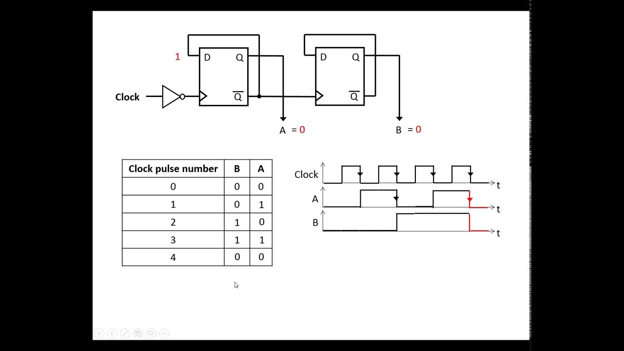
Circuit diagram of 3-bit synchronous counterDigital lab Bit circuit counter two has diagram solved following output transcribed problem text been show draw.

6 bit counter schematics. | Download Scientific Diagram

The 3-bit counter circuit. | Download Scientific Diagram

4 BIT up Counter and BCD Using Discrete Transistor

BCD Counter Circuit | Basic Electronics Tutorials
3 Bit Asynchronous Up Counter With Circuit Diagram And Truth Table

4-bit synchronous binary counter | Download Scientific Diagram